Layered crystals such as graphite are traditionally described using basal dislocations, but sufficiently confined compressive strain produces a different response. Molecular dynamics simulations reveal a progression from discrete dislocations, to distributed incommensurate strain, and finally to nanoscale elastic buckling (“ripplocations”). Rather than a new type of crystallographic defect, ripplocations emerge as a buckling instability that transfers strain out of the basal plane.
Approach
- Molecular dynamics simulations of graphite and related layered crystals
- Artificial confinement of excess material within individual layers
- Direct measurement of strain fields and interlayer disregistry
- Variation of pressure, elastic anisotropy, and number of compressed layers
Results
Dislocations, Incommensurate Strain, and Ripplocations
As compressive strain increases, the system passes through three distinct strain-accommodation regimes:
- Low strain: well-separated basal dislocations accommodate the excess material.
- Intermediate strains: confinement forces the dislocation cores to overlap, strain becomes distributed continuously throughout the layer, producing an incommensurate state with no clearly defined defects.
- High strain: the layer buckles out of plane and transfers energy into the surrounding crystal. This buckled state corresponds to the ripplocation.
Incommensurate strain and buckling are well-attested in bilayer graphene and similar systems, so this framework represents a natural extension to many-layered graphite systems.
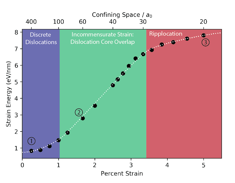
Figure 1:Confined Compression
Confinement of individual dislocations on a graphite layer reveals the transition to ripplocation structures. Increasing confinement of the dislocation increases the dislocation energy, until eventually buckled structures appear to relieve planar stress.
Figure 2:Ripplocation Dislocation Transition under Increasing Confinement
(Top) Strain fields created by compression of a single layer by one lattice unit, confined to a fixed region.
(Bottom)Top down view of the compressed graphite layer and reference layers. Darker regions show where the crystal structure is distorted. Overlay plot shows disregistry, quantification of distortion in the two planar directions.
Transition from Planar Strain to Buckling
The transition to buckling can be viewed simultaneously in physical space and on the generalized stacking-fault (GSF) energy surface. At low strain, dislocations follow preferred pathways between stacking minima. As confinement increases, the system abandons these discrete pathways and moves continuously across the energy landscape. Once buckling begins, part of the imposed strain is accommodated by out-of-plane bending rather than in-plane distortion.
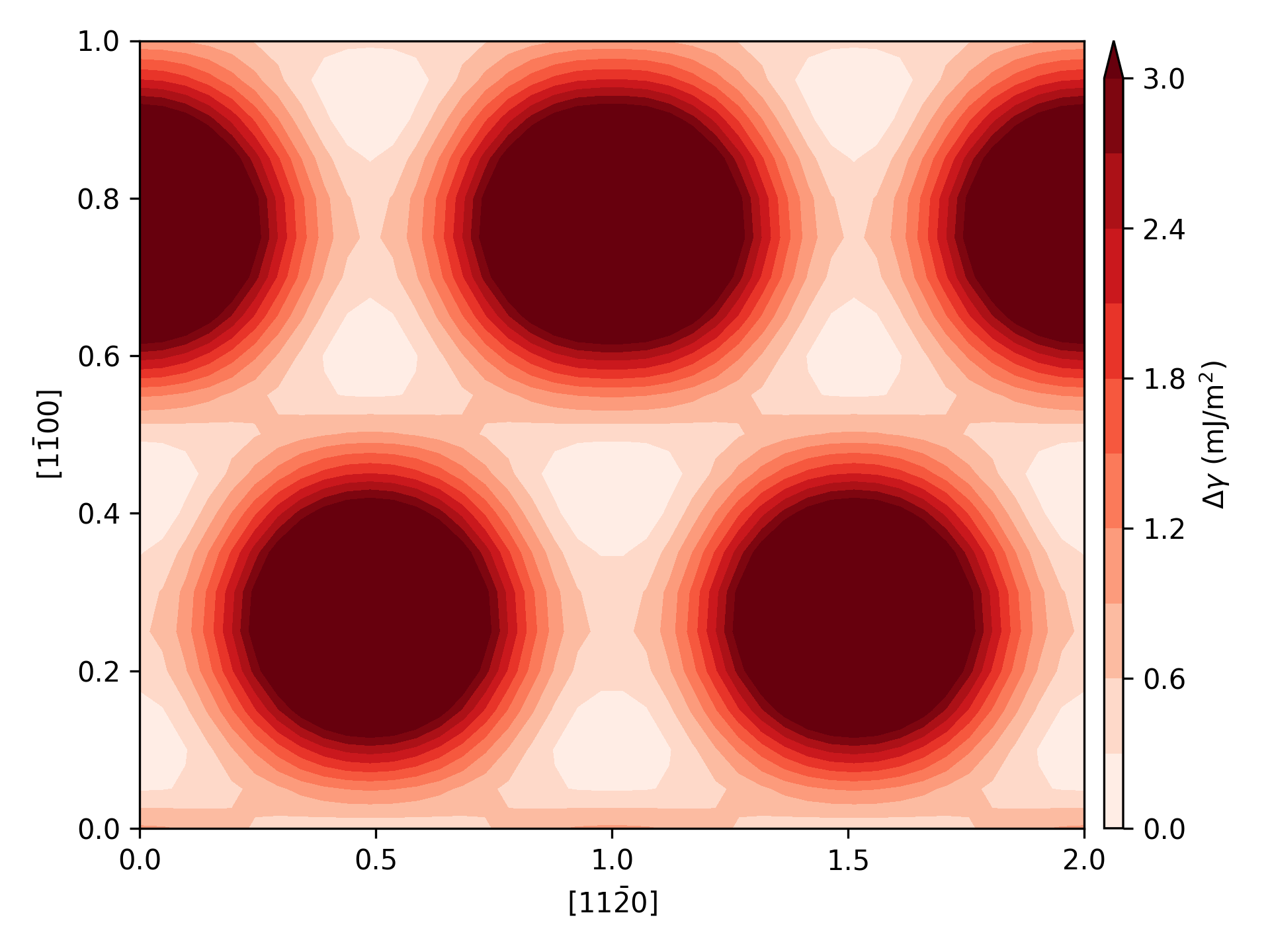
Figure 3:Interactive View
Interactive view showing the pathway on the GSF surface taken by the structure, a side view for showing out-of-plane buckling, and a top down view showing atom positions. The top down view shows the atoms within the boxed region of the side view, which can be moved with the mouse.
In planar configurations, the layers distort within the plane to bend around regions of high energy. At large strains, the layers buckle and, rather than going around the energy peaks, go directly over them.
Elastic Anisotropy influence on Buckling
The transition between the three regimes depends strongly on elastic anisotropy. Increasing pressure or strengthening interlayer bonding narrows dislocation cores and makes out-of-plane deformation more difficult. As a result, both the transition to incommensurate strain and the onset of buckling occur at larger compressive strains.
Figure 4:Dislocation Core Width Modulation
The dislocation core width is affected both by external overpressure normal to the layers, and by the bonding character of the solid. C_11/C_33 describes the anisotropy of the crystal, how much harder it is to compress the structure within the layers (C_11) vs normal to the layers (C_33).
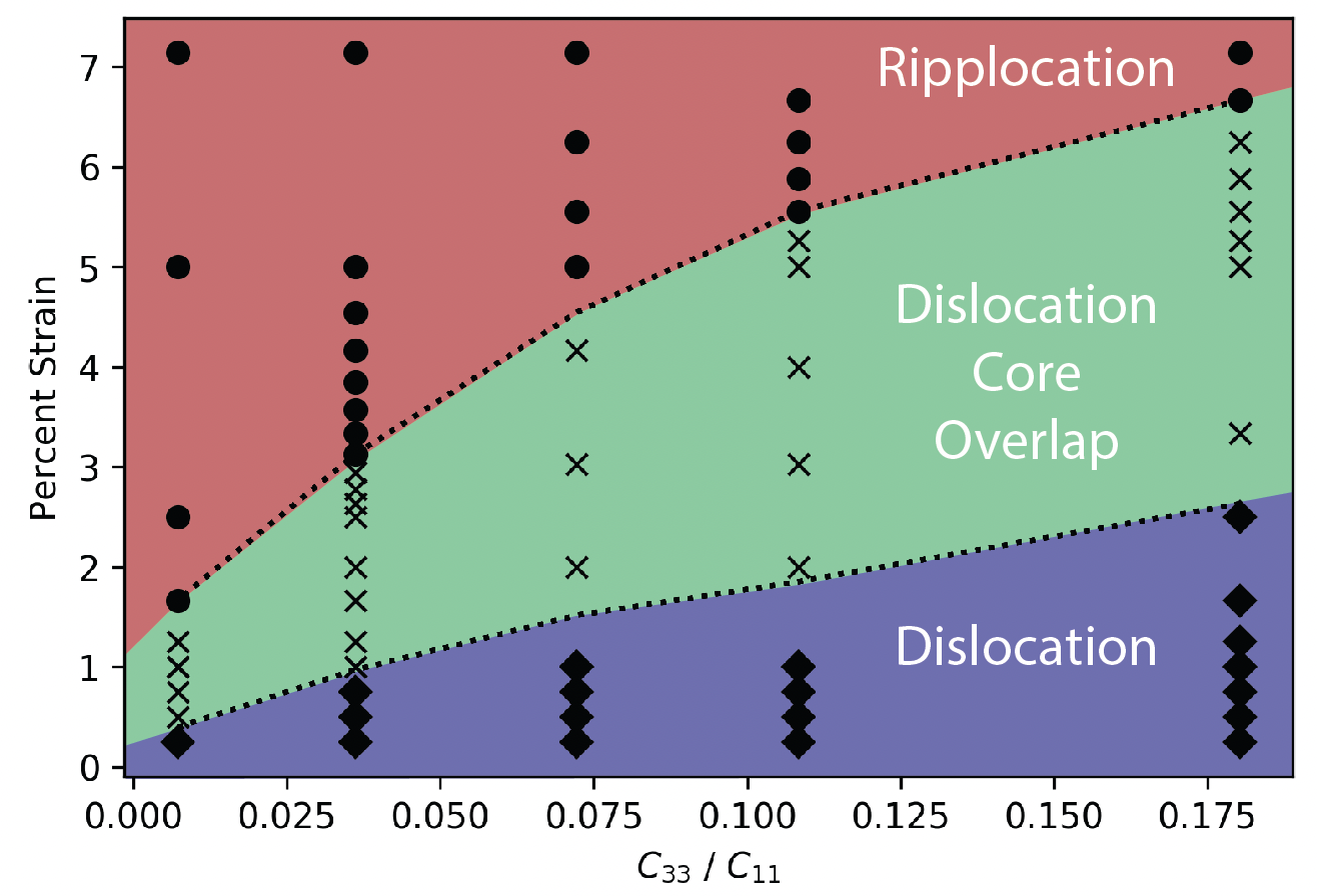
Figure 5:aniso
The transition to buckling is governed by the dislocation core width, and so by modulating the elastic anistropy, ripplocations can be relatively favored or inhibited. The stronger the bonds between the layers, the more difficult it is for buckles to form.
Collective Buckling of Multiple Layers
Buckling becomes significantly more favorable when multiple adjacent layers deform together. Neighboring buckled layers partially accommodate each other’s strain fields, reducing the energy cost per layer. Consequently, the critical strain for buckling decreases as the number of compressed layers increases.
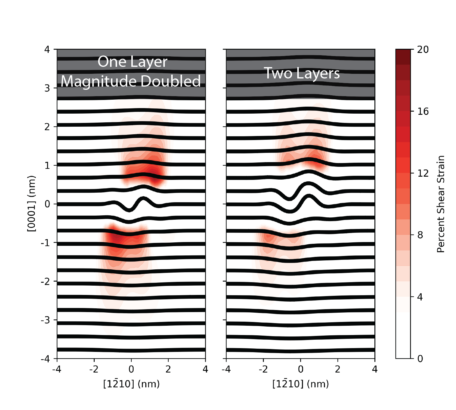
Figure 6:multilayer
Strain fields associated with a ripplocation on a single layer and a two-layer buckled structure. The energy per layer is far lower in the multi-layer case, suggesting that the single layer case is actually an extreme of a more general phenomenon.
Conclusion
These simulations suggest that ripplocations are best interpreted as nanoscale elastic buckles rather than a new class of crystallographic defect. The progression from dislocations to distributed strain and finally to buckling is controlled by confinement, interlayer bonding, and elastic anisotropy. Because collective buckling becomes easier as more layers participate, similar mechanisms may operate in a broad range of layered crystalline solids beyond graphite.
Further Reading
Bending the rules: Strain accommodation in layered crystalline solids through nanoscale buckling over dislocations
J. Gruber, G. Plummer, G.J. Tucker
Journal of the Mechanics and Physics of Solids
(2024)
[link]